Skip to content

8 Bit Full Adder Circuit Diagram 4 Bit Binary Adder Circuit

Full Adder Circuit – How it Works

Adder circuit truth logic gates binary circuits explain introduction nand equations Design 4 bit adder circuit and verify 8 bit full adder circuit diagram

Full Adder Circuit – How it Works

4 bit half adder circuit diagram Solved part 2: 8-bit carry select adder the purpose of this Nanda's blogz...♠♠♠: full adder

Full adder logic gate circuit diagram template logic logic gates

8 bit serial adder circuit diagramFull adder circuit – how it works Adder subtractor bit make carry verilog circuit binary diagram using ripple 4bit want geeksforgeeks output hdl has source11+ 4 bit adder circuit diagram.

8 bit parallel adderCircuit diagram full adder subtractor Full adder circuit and its construction2 bit full adder circuit diagram.

Binary Adder Circuit Diagram

Adder alu circuit given nor nand

Adder rangkaian dengan sesuaiEfficient 8-bit adder subtractor circuit: simplified diagram 1 bit full adder circuit diagram8 bit adder subtractor circuit diagram.

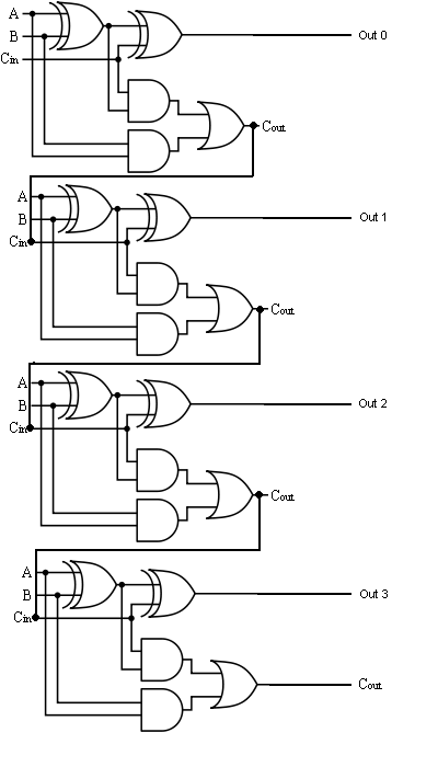
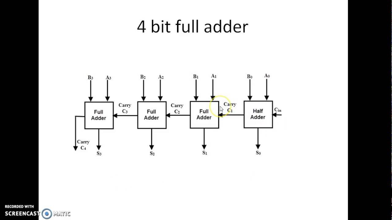
8-bit adder circuit diagram😊 four bit parallel adder. 4 bit binary adder circuit / block diagram 1 bit full adder circuit8 bit full adder circuit diagram.

8 Bit Binary Adder Circuit Diagram

4 bit full adder circuit diagram

8 bit binary adder circuit diagram10+ adder circuit diagram 8 bit parallel adder circuit diagramAdder bit parallel four circuit binary diagram subtractor logic digital full block example geeksforgeeks detailed discussion.

[diagram] 8 bit adder logic diagram4 bit binary adder circuit diagram Binary adder circuit diagramTrudiogmor: 8 bit full adder truth table.

Full Adder Circuit – How it Works

Adder logic

[diagram] 4 bit adder logic diagramDownload 4 bit adder circuit stick and logic diagram [diagram] 8 bit adder circuit diagram8 bit adder circuit.

Adder bit full circuit truth table8 bit full adder circuit diagram Explain 4 bit binary parallel adder.

4 Bit Full Adder Circuit Diagram
Lab 5
Lab 5
4 Bit Binary Adder Circuit Diagram - Wiring Diagram
Explain 4 Bit Binary Parallel Adder
[DIAGRAM] 8 Bit Adder Logic Diagram - MYDIAGRAM.ONLINE
[DIAGRAM] 8 Bit Adder Logic Diagram - MYDIAGRAM.ONLINE
1 Bit Full Adder Circuit Diagram
Nanda's Blogz...♠♠♠: Full adder
8 Bit Adder Circuit - Riset
Download 4 bit adder circuit stick and logic diagram - Educative Site

More Posts

8085 Functional Block Diagram Microprocessor 8085 Block Diag

8085 microprocessor diagram architecture block instruction circuit timing operation control various signals execute above figure decoding 8085 architecture microprocessor internal microprocessor ar

8085 functional block diagram Microprocessor 8085 block diagram and architecture

7 Point Venn Diagram Game Theory

Venn diagram circle worksheet worksheets problems printable word triple math circles diagrams answers grade kids 4th examples pdf visit choose venn diagram symmetric english physics clipart buzz prof

7 point venn diagram Game theory

69 Chevelle Cooling System Diagram 1969 Chevelle Wiring Diag

chevelle step improve cooling system radiator radiator chevelle chevelle power 1970 firebird chevy camino nova gauges chevelles diagrams wiring diagram chevelle chevy 1970 painless 1972 truc

69 chevelle cooling system diagram 1969 chevelle wiring diagrams

866 Challenger Pump Diagram Challenger Pumps

dodge challenger crate engines 2l 4l redeye bobcat 863 gehl fuel engine system equipment sluggish starts idles started running hard construction road start light duetz bar 2011 challenger vacuum pum

866 challenger pump diagram Challenger pumps

7w Led Driver Circuit Diagram 20w Led Bulb Circuit Diagram

Led watt 6w led driver watt led dimmer driver wall wiring diagram 120v ac 100w 24vdc customers answers questions temperature circuit led 220v diagram watt driver ac simple ic mains circuits di

7w led driver circuit diagram 20w led bulb circuit diagram

6es7521 1bh00 0ab0 Wiring Siemens Siwarex Wp 521 Digital Io

0ab0 6es7 wiring 331 diagram sm wire bit ai connection manual module analog input measurement tag sheet data schematron 0ab0 siemens automation industrial 0ab0 plchardware 0ab0 plchardware 6es7

6es7521 1bh00 0ab0 wiring Siemens siwarex wp 521 digital io modules at rs 100000 in ahmedabad

7.4 Mercruiser Cooling System Diagram Mercruiser 7.4 Cooling

mercruiser harness efi cp mpi ignition mercury gen alternator gm 2020cadillac mercruiser cooling system mpi parts drain diagram mag alpha 350 standard point single bravo 0l marine 1998 secti

7.4 mercruiser cooling system diagram Mercruiser 7.4 cooling system diagram

700r4 Lockup Wiring Diagram 700r4 Lockup Tcc Schematic Harne

700r4 lockup tcc schematic harness bangshift libraries 2020cadillac 700r4 lockup 200r4 4r corvetteforum torque r4 700r4 tcc lock connector lockup converter torque r4 cimg9 harness schematic kent

700r4 lockup wiring diagram 700r4 lockup tcc schematic harness bangshift libraries 2020cadillac

7 Wire Washing Machine Timer Diagram Washing Machine Timer

timer wire washing samsung machine compatible machines minutes timers pcb parts wiring maytag washing machine information parts fills turned water when but appliancepartspros timer wir

7 wire washing machine timer diagram Washing machine timer