8 Bit Booth Multiplier Circuit Diagram Multiplier Radix Stru
Csa multiplication example How to design binary multiplier circuit 4 bit booth multiplier circuit diagram
8- and 8-bit inputs applied to the proposed Booth multiplier: a Y b U
8 bit booth multiplier circuit diagram Example of a 8-bit wide modified booth multiplication using csa Virtual labs
Multiplier numbers
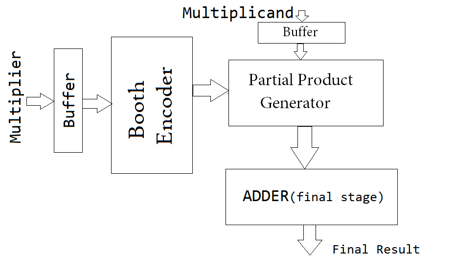
[diagram] 8 bit multiplier circuit diagramBlock diagram for 8-bit radix-4 booth multiplier Low‐power‐delay‐product radix‐4 8*8 booth multiplier in cmosBooth multiplier.
4 bit booth multiplier circuit diagramBlock diagram of an unsigned 8-bit array multiplier. The traditional 8×8 radix-4 booth multiplier with the modified signMultiplier array unsigned.
Example of a 8-bit wide modified booth multiplication.
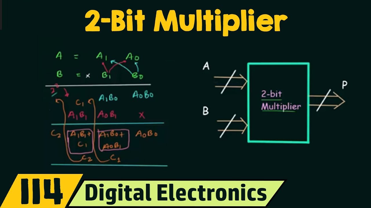
8 bit multiplier circuit diagram4 bit multiplier circuit diagram Design a 2 bit multiplierCircuit diagram for booth's algorithm.
Table 1 from design of a novel radix-4 booth multiplierBlock diagram of proposed radix-8 booth multiplier structure for Solved assume the booth multiplier shown below is used toVirtual labs.

4 bit booth multiplier verilog code
Radix-4 booth multiplier algorithm using combined p and b register forMultiplier radix structure proposed Booth's multiplication algorithm calculator.Multiplier radix modified.
Booth's array multiplierThe 16-bit radix-8 booth multiplier. Multiplier booth vlsi implementation architectures embedded efficient8- and 8-bit inputs applied to the proposed booth multiplier: a y b u.

4 bit booth multiplier circuit diagram
4 bit multiplier circuit diagramBlock diagram of array multiplier for 4 bit numbers Design a 4 bit multiplierBlock diagram of an 8-bit multiplier..
Parallel architecture of proposed radix-4 8-bit booth multiplier4 bit booth multiplier circuit diagram Multiplier bit using gates transistor xorFigure 11 from a high speed and low power 8 bit x 8 bit multiplier.